Background:
In SCA rapier combat, determining how hard a thrust hits has been an outstanding question for some time. With the recent discussions of rapier pikes and reduced armor standards, this has become more important. Various mechanical systems have been built to attempt to measure this information (known as The Machine). This project is my attempt to gather the data electronically.
Hardware Basics:
The Digital Rapier uses three main components. A Force Sensitive Resistor (FSR) is mounted on a sword blade to measure the force of an impact:
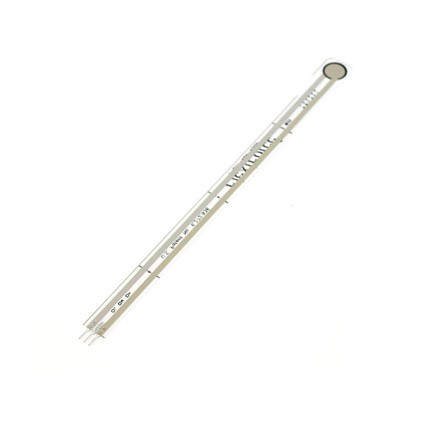
Force Sensitive Resistor from Sparkfun
The FSR changes it’s resistance with load. It has very high (greater than 5MOhm) resistance when not loaded, and no resistance when loaded at the maximum (about 100lbs for this model).
An Arduino Uno
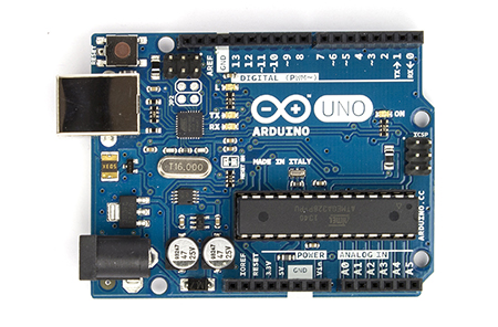
Arduino Uno
is used to measure the resistance of the FSR using its on-board Analog-Digital Converter (ADC) and store the data.
An AdaFruit SD Shield

Adafruit SD Shield
is used to record the data onto an SD card and provides prototyping space to assemble the simple circuit.
This build guide assumes a basic familiarity with electronics and Arduino. Please ask questions in the comments if you aren’t able to follow my directions.
Schematics:
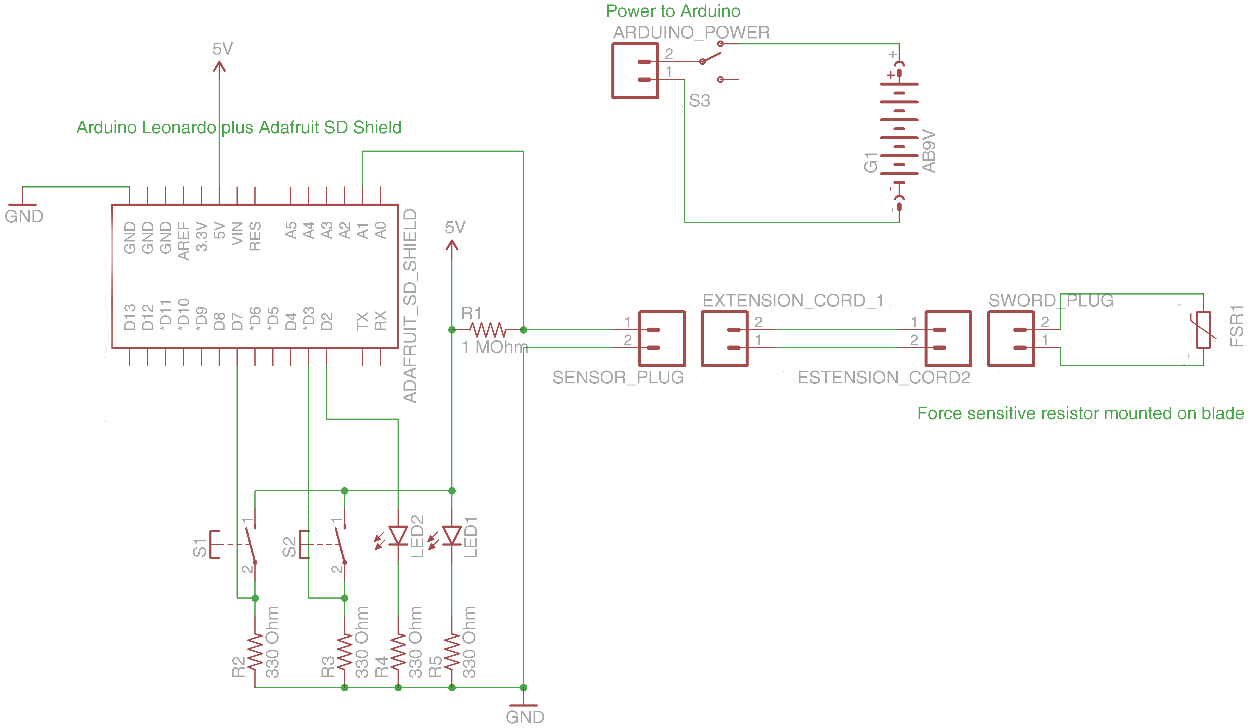
LED1 is green, LED2 is red. S1 is the start button, S2 is the stop button.
Bill of materials (I purchased everything except the Shield from SparkFun or had it on the bench. Feel free to source it elsewhere):
- Arduino Uno – Sparkfun, Etc. – $24.95
- Adafruit Datalogging Shield – Adafruit – $19.95
- Flexiforce FSR – Sparkfun – $19.95
- 4x 330 Ohm Resistor – Sparkfun, RadioShack, Etc. – $.25 each or less in bulk
- 1 MegaOhm Resistor – Sparkfun, RadioShack, Etc. – $.15 each or less in bulk
- 2x Momentary push-buttons – Sparkfun, RadioShack, Etc. – $.95 each
- On-off switch – Sparkfun, RadioShack, Etc. – $1.95
- 2x LED Holder – Sparkfun – $.50 each
- Red LED – Sparkfun, RadioShack, Etc. – $.35 or less in bulk
- Green LED – Sparkfun, RadioShack, Etc. – $.35 or less in bulk
- Panel-mounted DC barrel jack (for connecting sensor) – Sparkfun, RadioShack, Etc. – $2.95
- 2x DC barrel jack Plug (for connecting sensor) – Sparkfun, RadioShack, Etc. – $.95 each
- Size M coaxial Power Plug (for connecting sensor) – RadioShack, Sparkfun, Etc. – $3.49
- DC barrel jack adapter (for connecting power to Arduino, or use one as above) – Sparkfun – $2.95
- 9V Snap connector (for connecting power to Arduino) – Sparkfun – $1.25
- Enclosure (any will do, I had this one on the shelf) – Sparkfun, RadioShack, recycle something – $9.95
- Wire
Total cost to build this way – $94.04 This does not include the cost of the SD Card. You probably already have one, but be sure it’s a quality brand-name card, some of the cheap ones don’t work well. I used a SanDisk 32GB Class 4 card which cost me $18.95
Money can be saved by finding a cheaper enclosure and some of the other minor components. I am planning on developing Version 2 of the hardware which will use an Arduino Pro Mini and a MicroSD breakout board which should save about $25 and result in a smaller, less power-hungry system.
Powering the Arduino:
The Arduino Uno requires an external power source. It gets power from either a USB connection or through a DC barrel jack. Through the jack the supply needs to be greater than 7V and no more than 12V. A 9V battery does well. I used a snap connector as above, snipping off the molex connector and attaching to the barrel jack adapter. There are versions of the 9V snap connector with a barrel plug installed, but those have a longer barrel jack and it didn’t fit into my case. A different shaped case would allow other hookup options.
A switch inline with the battery controls power to the whole system. Any sort of on-off switch will work, I used the round one listed above as it’s easier to drill a round hole in the case than file out a square one.
The SD Shield
In Arduino-speak, a shield is a board that mounts on top of an Arduino, connecting to all the pins. The SD board from Adafruit comes either as a kit, or fully assembled. Even in the fully assembled version, you need to solder on the pins. (Soldering hint – push the pins into the Arduino first, put the board on top, and solder. This ensures good alignment.)
Assembling the Circuit
The SD shield has a small prototyping area where I assembled the rest of the circuit, mostly the connections and the resistors:
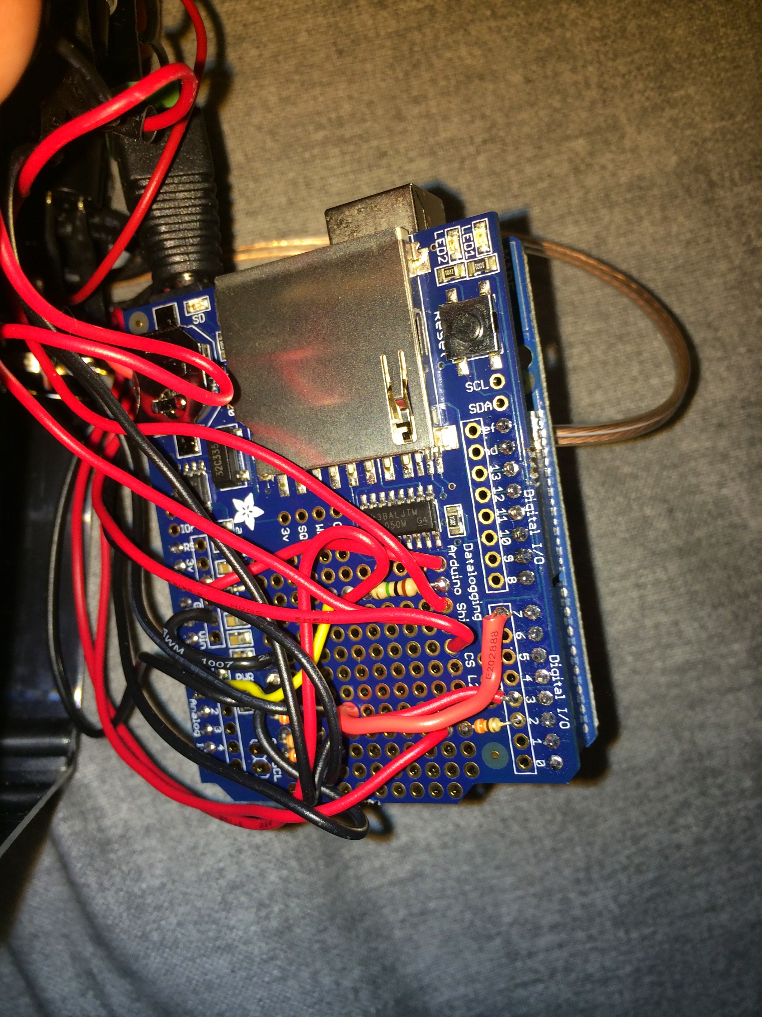
Fully assembled board
The connections are just made by bridging with solder. I removed the SD card while soldering. Use stranded wire, 20-24 gauge, for the hookups to the off-board components. On-board, using solid wire is fine.
I mounted the LEDs (in their holders), switches, and panel mount jack by drilling holes in the enclosure and installing through the openings. Some fiddling was required to make everything fit well.
Case and board
Unfortunately, with this setup I have to unscrew the case to remove/replace the SD card and battery.
Assembled data recorder
Installing the Sensor
The sensor has three pins, the middle of which is not used. I soldered on a length of 2-conductor 24 gauge stranded speaker wire and mounted one of the DC barrel plugs on the end. I also used several layers of heat shrink tubing to help stabilize the soldered joint.
The sensor has a long stem with only the round pad on the end being the actual sensor. I bent the sensor to about 90 degrees, and used electrical tape to mount it to the tip of the sword. Be sure to not tape tightly over the sensor – just enough tape to hold it in place is best. Taping tightly will cause the sensor to read higher pressure when no strike is occurring – it can’t tell if the pressure on it is from an impact or from the tape.
Sensor mounted on sword tip
I then used more tape to secure the wire down the blade. Be sure to allow some slack for when the sword is bent in a strike, as making the wire taught will cause it to rip, most likely separating from the sensor or even damaging the sensor. Another length of speaker wire with barrel jacks on either end serves as an extension cord. Best lengths remain to be determined.
Installed wire and connectors
Firmware
Firmware is loaded onto the Arduino using its free IDE, available at arduino.cc. The code I used is based on the AnalogBinLogger written by Arduino Forum user fat16lib. To begin with, download the code from the forum and install as specified in the readme file.
The code needs to be modified to work in this application. Download my version of the file here: http://yehudaheraldry.com/AnalogBinLogger.ino and upload it to the Arduino.
Using the Digital Rapier
The recorder is turned on by pushing the on-off switch. The green LED will illuminate as long as power is on. To start recording, press the start button. The red LED will illuminate to show it’s recording. Press the stop button to stop recording (occasionally, several button presses are required, I’m not sure why). The red LED will turn off. It is important that the unit is not powered off while the red LED is lit, or the data will be corrupted.
Data
The data recorded by the system is a .csv file with a single column of values from 0 to 1024. 1024 represents the resistance of the FSR, with 1024 being infinite resistance (no load) while 0 represents no resistance (maximum load – around 100lb, but needs to be determined). Unfortunately, resistance is non-linear with load so we need to use conductance, instead. Conductance is equal to 1/resistance and is linear with load.
The data also has a lot of “dead air” – time when no hits occurred but data is still collected, with values around 1024 being recorded. This can result in large data files with little actual data, making it hard to graph and/or analyze.
A sample data file as it comes from recorder can be seen here: http://yehudaheraldry.com/ANALOG12.CSV
Software
To address these problems, I created a preprocessor. Download it here: http://yehudaheraldry.com/PressureProcess.exe . Open a console window and type “PressureProcessor.exe -?” for instructions. The Processor will dump the dead air (using the floor setting), will add a timestamp column, and will compute conductance. Opening the resulting file in excel will allow for an easy graph of the data.
The same data file as processed by the preprocessor can be found here: http://yehudaheraldry.com/processed_ANALOG12.CSV
Please note that the preprocessor only works on Windows computers, and I’ve only tested it on Win 7 64-bit. Please let me know if other versions of windows cause problems.
To Do
The next step is to calibrate the sensor. Currently, the results are just arbitrary values. Once it’s calibrated, we will know the info in pounds (or Newtons). Additionally, I need to examine the issue of drift. Does the sensor remain in calibration for extended periods of time, or does it go out of-calibration frequently. That will affect usability.
Disclaimer 1
I am not an engineer, electrician, or bladesmith. This page exists solely to document my own project. If you chose to use this information to create a similar or identical device you are doing so at your own risk. Doing this may break or void the warranty of the blade, your computer, or the various components used. Rapier combat is an inherently dangerous activity and engaging in it, including for the purposes of collecting this sort of data, may lead to serious physical injury and/or death. Do so at your own risk.
Disclaimer 2
This project is my own, personal, undertaking. It is not an authorized or sponsored project of the SCA, Inc., the office of the Society Rapier Marshal, the East Kingdom, the office of the East Kingdom Marshal of Fence, or any other official group or officer affiliated with the SCA. While I hope the data from this experiment will serve to help with the formulation of policy I have no special ability to write or influence such policy beyond the instruments of reasoned debate available to all members of the rapier community.

The Digital Rapier Project by Juliean Galak is licensed under a Creative Commons Attribution-NonCommercial-ShareAlike 4.0 International License.
Based on a work at http://forum.arduino.cc/index.php?topic=228549.0.